In the following two tutorials (Part 4 and Part 5), we will refine each of the rulesets that we have created in this tutorial series. In this tutorial, you will refine the first ruleset you created, My First Ruleset, then create a classification for MEP systems, and finally create two rule variations for a specific rule.
Note
The video related to this tutorial article can be found here.
This tutorial covers the following topics:
No issues have been created in our project (either added as slides to be used in presentations or uploaded via BCF Live), so we can look into refining the rules without any consequences. The process for editing rules where issues have been created can be followed from the resource revision management movie.
Rules may need to be refined due to many reasons, issues with the original configuration, definition of precheck rules to catch modelling issues, missing data, exposure to different models, changing standards or project deliverables, to name but a few.
Important
Creating new rulesets or adding new rules to existing rulesets will not create problems, however, editing existing rulesets and resources, if they are used within rules, can result in removed issues or at best orphaned slides in presentations.
Please note that any referenced data, property, or classified elements used within a rule, if changed, may affect the results of the rule.
As a precaution, any changes to rulesets or resources that may affect rule results, where issues have been created in a project, should be carried out either in a different model or a copy of the production model.
Examples of rule refinement can be generally categorised into the following key areas:
-
Data Variations: locality of data may be tackled in three ways.
-
Rectify the data location within the rule adopting the correct location.
-
Define and ensure Ifc files are created in line with the data requirements of the project i.e. required property/property set names. Authoring applications generally allow the user to create custom mappings on export to IFC.
-
Where this is not possible with data found in inconsistent locations, classifications within Solibri can be used to collate data.
-
-
Rule not functioning as ordinally designed
-
Correct the rule so that it performs as required. Changes to rules where issues have been created from the results, can be carried out by editing the rule in a copy of the project. Follow the instructions in the resource revision management movie.
-
-
Missing data or incorrect geometry
-
Where rules do not run correctly due to missing information or geometry incorrectly specified, pre check rules can be set up to detect these situations. The results can either provide data to sub-rules or act to inform the user.
-
In our first ruleset, we created a General Intersection Rule which detects clashes between MEP and structural elements.
Prior to running the clash check in My First Ruleset, creating pre-clash checks for the individual consultants' models will identify any unnecessary or duplicate issues when checking the federated model. These can be conveyed to the consultants or in-house teams, producing a clean model in which to start interdisciplinary checks.
When refining this ruleset, we will introduce the use of wildcards (*) and classifications.
First, we'll refine the clash rule in My First Ruleset:
-
Open the Rulesets model created in the previous tutorials.
-
Go to Ruleset Manager.
-
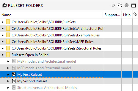
In the Ruleset Folders view, open the Rulesets Open in Solibri folder and select My First Ruleset:
-
Click
 in the Workspace view:
The ruleset you selected is opened.
-
Right click on the MEP Vs Structural Rule and select Copy from the context menu:

-
Right click on the root folder (My First Ruleset) and paste a copy of the rule. Select the first instance of this rule in the Workspace view and rename it to Pre-Clash Checks - Structural in the Info view:

-
In the Parameters view, click
 in the Component 2 table to save the filter:
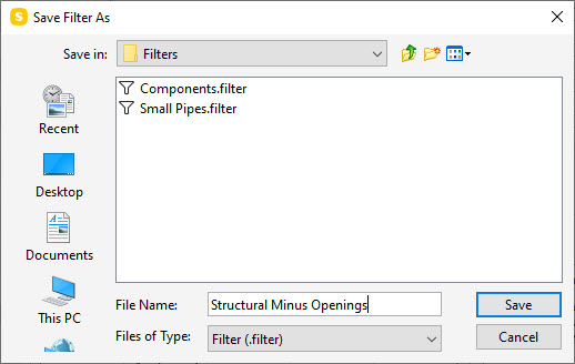
The saved filter can then be applied to Component 1. Name this filter Structural Minus Openings and click Save:
-
To load the same filter for Component 1, click
 . Select the Structural Minus Openings filter and click Open. You now have the same filter in use for both components, which means that we are now checking components in the structural model against each other:
-
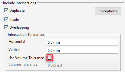
In the Parameters view, uncheck Use Volume Tolerance:
Next, we need to replicate this process to add a pre-check for the MEP model:
-
In the Workspace view, select the Pre-Clash Checks – Structural rule, create a copy and paste the copy on the My First Ruleset folder. This creates the new copy of the rule at the bottom of the list. Move it above the MEP vs Structural rule using the Up arrow in the toolbar.

Tip
If you accidentally placed a copy inside another rule and inadvertently created a gatekeeper rule, you can resolve this by dragging the new rule to the top level (My First Ruleset).
-
In the Info view, rename this version Pre Clash Checks - MEP.

-
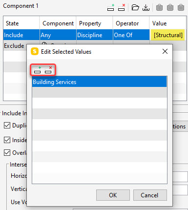
Change the Component 1 values. Double click the Value cell and remove the Structural discipline by clicking
 . To add Building Services instead, click
  and select it from the list. To close the dialog, click OK:
-
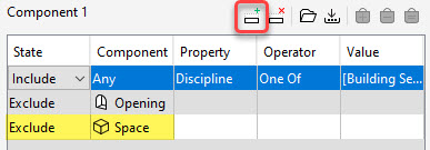
To exclude spaces, add another row to the Component 1 filter by clicking
 . Set the State to Exclude and Component to Space:
-
Save this filter with the name MEP Minus Spaces and Openings.
-
Load the saved filter also for Component 2.

To see the effects of the changes, go back to the Checking layout and rerun the rules by clicking Check Model.
Results - Structural:

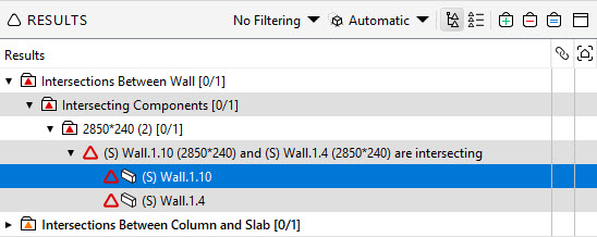
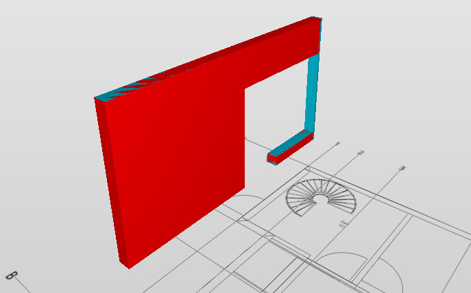
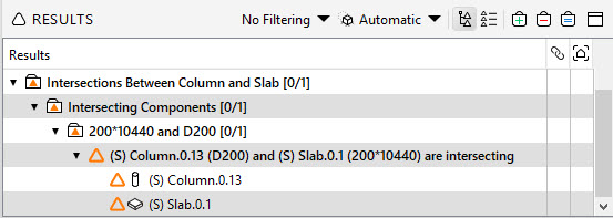
The structural pre-check rule identifies two issues:
-
A wall that is almost a duplicate:
-
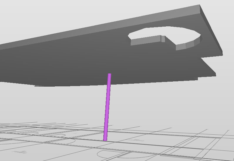
A clash between a column and slab:
-
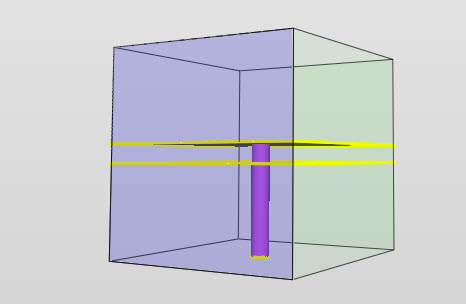
To help visualise the intersection of the column and slab, right-click on the issue in the Results view and select Section Box from the context menu. This will show the issue components in context with the model.
-
To visualise only the issue components, click
 in the Results view toolbar:
-
To return the model to the default state, click
 in the main toolbar.
Results - MEP:

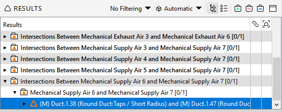
The MEP pre-check shows clashes between the different sub systems. With the default settings, it will ignore any clashes that are in the same sub system.
-
Select the last issue in the Results view.
-
To zoom in, double-click on the issue. Right click on the horizontal duct in the 3D view and then select Make transparent from the context menu:

-
To show the intersection, add a section plane by pressing 0 (zero) on your keyboard (or select the Sectioning tool from the main toolbar) and then clicking the duct surface. To move the section plane, press Shift while moving your mouse wheel:

-
To return the model to the default state, click
 in the main toolbar.
 -
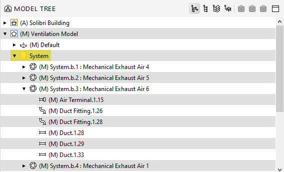
The default option for the general intersection rule ignores intersections when components are in the same system:

The definition of the system can be seen from the Model Tree view in the Model layout in the Containment hierarchy under Systems:
-
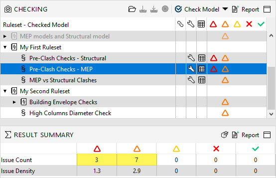
Go to the Checking layout. Select the MEP rule in the Checking view and then observe the number of issues in the Results Summary view. The rule detects 10 issues in total, 3 critical and 7 moderate:
-
In the Checking view, right click on the MEP rule and select Rule Parameters from the context menu.
-
Turn off the In the same system option:

It will now create intersections for elements in the same system.
Tip
If your model supports the use of layers, another option would be to use layers to ignore issues (In the same layer and model).
-
Close the rule parameters and click Check Model.
-
By changing this parameter, the issue count increases to 21, of which 3 are critical and 18 moderate:
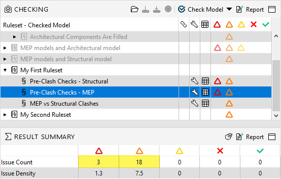
Now the rule highlights overlaps that are occurring in the same system:

If you need to check one parent system against another, you can use the system name from the Identification tab in the Info view, along with a wild card to omit the additional individual sub system numbers:
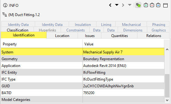
You could use another property, if available, where it contains only the value of the parent system name.
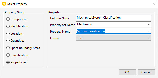
In this model we have a parameter in a property set (Mechanical) called System Classification that provides the parent system name:
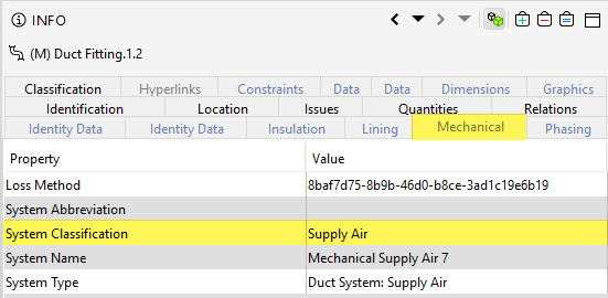
Next, we will create two rules, which essentially produce the same result but utilise different methods: one uses the system name with a wildcard (*) to omit the system numbers, and the other obtains the data through a user-defined classification, accessing the previously identified parameter. Although you could link directly to this parameter, creating a classification provides other benefits.
Classification creation:
-
Go to the Information Takeoff layout.
-
Close any resource loading dialogue which may appear by clicking Cancel.
-
To create a new classification, click
 in the Classification view toolbar.
 -
The Classification Settings dialog opens. Name the classification MEP Systems.
Important
The name of the classification is the only link to any rule that references it, therefore ensure that this value, once used within a rule, is not edited.
-
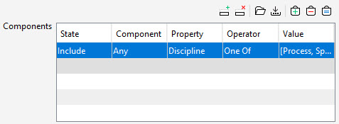
In the Components filter, change the Property to Discipline, Operator to One of and pick all the different discipline values that could make up M&E models (Air Conditioning, Building Services, Cooling, Electrical, HVAC, Heat, Process, Special Piping, Sprinkler and Ventilation):
-
Go to the Classification Rules tab. Right click on the Type column and select Remove Column from the context menu. Remove also the Layer column. You're left with the Component, Name and Classification Name columns.
Note
We will use only one property for obtaining values. If data exists in different locations for other models, then you can utilise the additional columns to set priorities for classifying data.
-
Double click on the Name column header (or right click and select Edit Column) and change the radio button option to Property Sets. Change the property set name to Mechanical and the Property Name to System Classification:
-
To close the dialog, click OK.
-
To add a row to the table, click
 .
. -
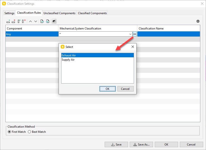
Click the Mechanical.System Classification cell. To see the values contained in our defined field in relation to the filtered elements from the Settings tab, click
 . You can see the two values Exhaust Air and Supply Air:
-
Close the dialog by clicking Cancel and leave the value with the wildcard (*).
-
Click the Classification Name cell. Click = and select =2 (Mechanical.System Classification):
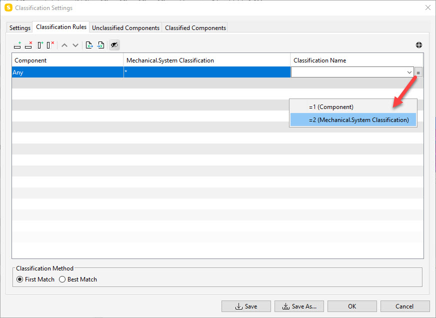
This will automatically categorise the components based on the field value contained in the second column.
-
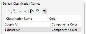
Go back to the Settings tab. To add two new rows to the filter in the Default Classification Names area, click twice on
 .
.Two values are automatically created with the default colour value. This adopts the colour of the original IFC component:
-
Double click on the Component Colour cell for Supply Air. Select a colour from the colour chooser and click OK.
-
Repeat this process for the Exhaust Air.
-
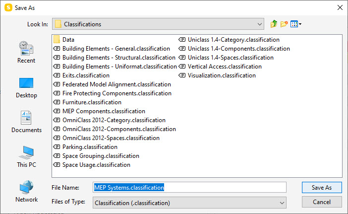
Click Save As. A dialog opens. Save the MEP Systems classification to your default resource directory:
Tip
If you want to reuse this classification in your role, you can save it externally at this stage. Otherwise it will only exist in this project. When you're closing the model, you will be asked if you want to save a version externally.
-
To close the Classification Settings dialog, click OK. You can see that the model shows the MEP system with the colours you have just defined:
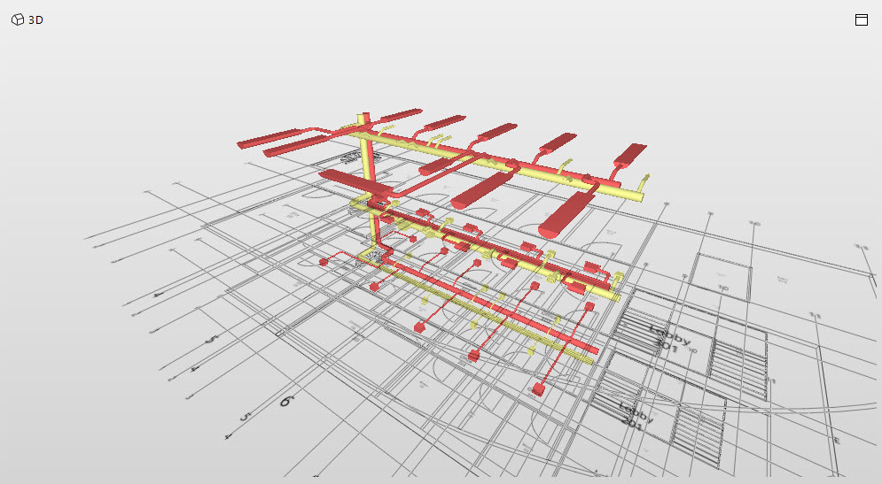
Opening the arrow to the left of the classification shows the two systems assigned with our colour selection.

To isolate the components related to the category, click on either of these systems.
-
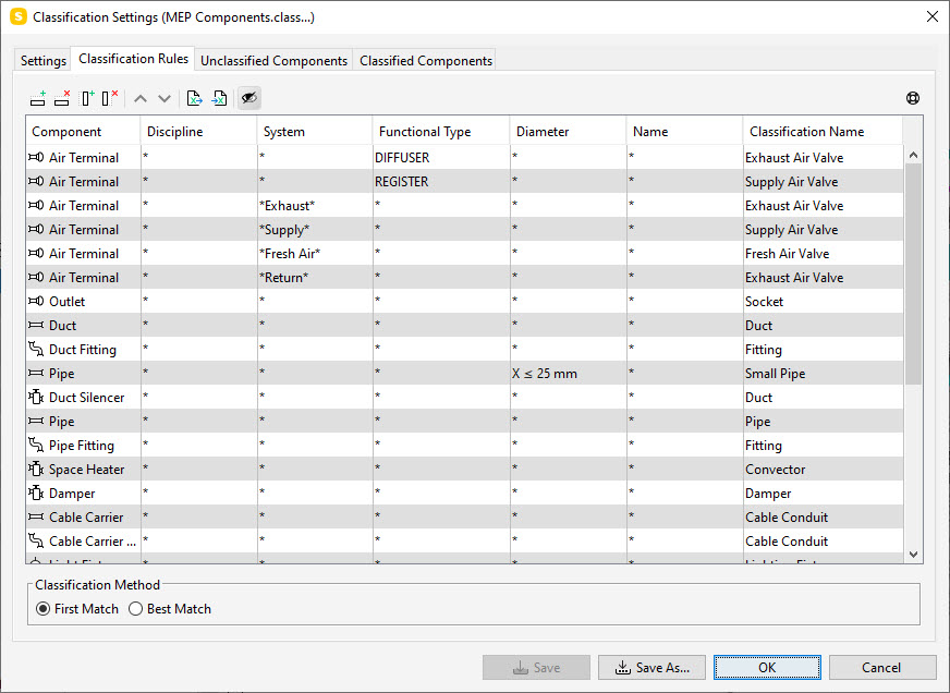
In the Classification view, you will also find another classification, MEP Components. This was automatically loaded when we originally opened the file using the BIM coordination role:
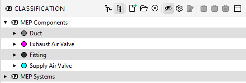
Select the MEP Components classification and then click
 in the Classification view toolbar. The Classification Settings dialog opens on the Classification Rules tab.
 -
The Classification rules indicate the criteria used to create the categories. In this example, user-based values are created based on the criteria columns for the Classification name:
Go to the Settings tab and observe the colour settings for the classification names:
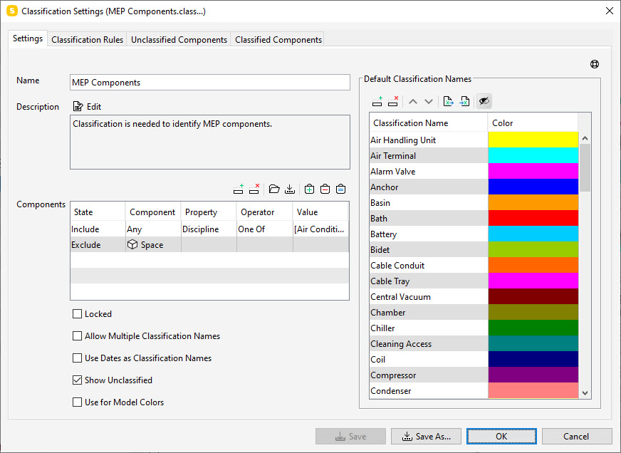
The model displays the components based on a user-based categorisation. Unlike our MEP Systems classification, these values are user-defined and do not exist in the original model, but can be used to map models from different authors to a standard, if required.
-
To close the dialog, click OK.
We can now return to Ruleset Manager to create the two rule variations.
-
Go back to Ruleset Manager.
-
In the Workspace view, copy the Pre-Clash Checks - MEP rule and paste it on to My First Ruleset. Move it under the original Pre-Clash Checks – MEP rule using the
 button.
 -
Rename the rule to Exhaust vs Supply - Wildcard Property Method:

-
In the Parameters view, change the Property value for Component 1 to System. Change the Operator to Contains and then double click the Value cell and type Exhaust*.
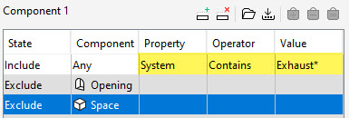
Using the wildcard ensures that we are including the whole system, not just the individual sub system.
-
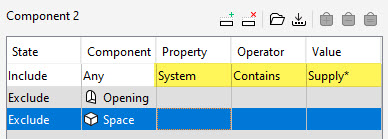
Repeat the process for Component 2, but this time insert Supply* into the Value cell:
-
In the Workspace view, copy and paste this new rule on to My First Ruleset. Move the rule under the original Exhaust vs Supply - Wildcard Property Method rule using the
 button.
 -
Rename this rule to Exhaust Vs Supply - Classification Method:

-
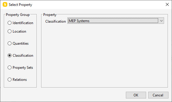
In the Parameters view, edit the Property value for Component 1. Click
 and select Classification from the radio button list. From the drop-down menu, select the MEP Systems classification we created earlier:
-
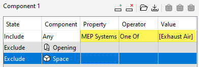
Change the Operator to One of. Double-click the Value cell and select Exhaust Air from the value list:
-
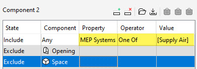
Repeat the process for Component 2, this time selecting Supply Air from the list:
-
To save your ruleset, click
 in the Workspace view.
 -
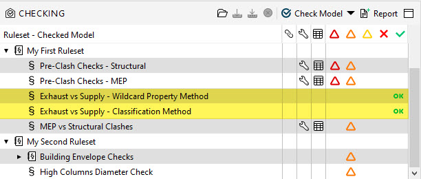
Return to the Checking layout and re-check your rules by clicking Check Model. There shouldn't be any inter-system clashes in either of the two rules:
-
Save the model and exit Solibri.
Note
If you do not save any of your resources, or changes have occurred since the last external save, Solibri will prompt you again to save on closing the project. If you only save the model (which is the default option), then all resources will still exist in the saved project.